TotalSim Aerospace Industry CFD Solutions
Totalsim’s solutions for the aerospace industry enable you to account for all aspects of plane performance. We’ve streamlined the process of modeling complex physics in aerospace propulsion, wing performance and aerodynamic CFD simulations. We easily visualize results helping you to evaluate and improve your designs. Explore our Aerospace capabilities below.
Aerodynamics Simulation Service
Propulsion System Modeling Service
Cabin Systems Consultant Service
Space Systems CFD Expert Services
Totalsim Workflows in Computational Fluid Dynamics as an Aerospace design tool:
TotalSim's motor-sports technology has been borrowed for aerospace engineering workflows with complex CFD requirements.
TotalSim aerospace workflows aim to create a digital-twin to the aircraft design process. Our technology was born in the automotive F1 race track and can be employed to address critical flight issues.
The following workflow capabilities provide an overview of the accomplishments in aircraft design using our StarCCM+ workflows for the most complex challenges that require CFD technology for resolution.
Benefits We Provide
Working with virtual modeling and simulation of fluid flows allows you to accelerate your design process using software such as Star-CCM+ or OpenFOAM. This reduces the number of physical prototypes and testing, while still evaluating all necessary conditions. Our engagement ranges from CFD consulting, to training, to customized workflows that meet your specific needs.
Our simulations help save you time and money while providing valuable insights. Whether you are testing wing design, propulsion or investigating the effects of Ground Vibration Tests (GVT), our personalized simulations and apps provide assist you. Working with TotalSim will put you years ahead of the competition, while simultaneously lowering your costs and optimizing your designs. Let us help you reach your goals efficiently and accurately.
Learn About Our Aerospace Capabilities
Aerodynamics - Conventional Aircraft
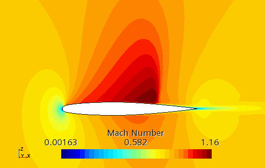
CFD Transonic Airflow Analysis
Our workflow helps customers calculate flow of air around an object at a speeds that generates regions of both subsonic and supersonic flow. Our workflow is able to handle this kind of flow characterized by :
- Subsonic Free-Stream Flow
- Supersonic on the Suction Side of the Airfoil
- Subsonic Through A Shock Wave
- Validate to Experimental Data
- Reduce Unsteadiness to the Flow Around the Vehicle
Wing Design
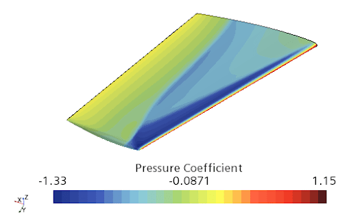
TotalSim's workflow uses meshing techniques for complex aerospace geometries such as wings, propeller blades and turbine blades. The fine mesh adequately captures the curvature of the leading and trailing edges using any operating condition like Free-Stream Mach Number, Angle of Attack, Reynolds Number, Mean Aerodynamic Chord, Free-Stream Velocity and identify:
- Transonic Flow
- Pressure Around the Wing
- Validate Experiments Faster
- Visualize Shock Waves Location and Reduce Airflow Separation Downstream
- Increasing Lift and Reduce Drag Coefficients
- Distribution of Pressure Coefficient Over the Airfoil Surface

Fuselage Design
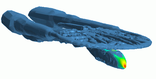
Our rotor - fuselage workflow allows us to include operating conditions that exerts a wide range of loads to the fuselage from a variety of sources to calculate:
- Fuselage Bend Downwards from its Support at the Wing
- Wind Loads from the Rotor and Free Stream Velocity
- Pressure Due to Rotor - Fuselage Interaction in Maneuvering Flight and Landing Loads
Control Surfaces
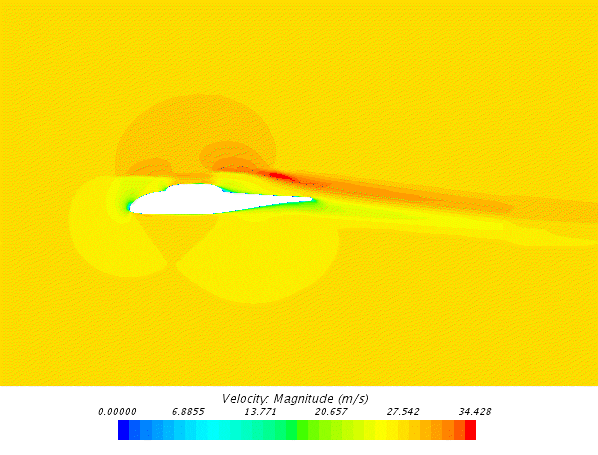
Our workflow automatically modifies the values of design parameters and evaluates the resulting lift and drag coefficients of a control surface design. By adjusting the position of the leading and trailing flaps configurations we can help our customers to evaluate designs as follows:
- Optimize Flaps Based on Objectives
- Maximize Lift while Minimizing Drag
- Reduce Flutter Potential that Could Destroy the Wing
- Explore over 120 Designs with the Optimization Tool
- Set Design Parameters to Control the Position of the Airfoil Flaps
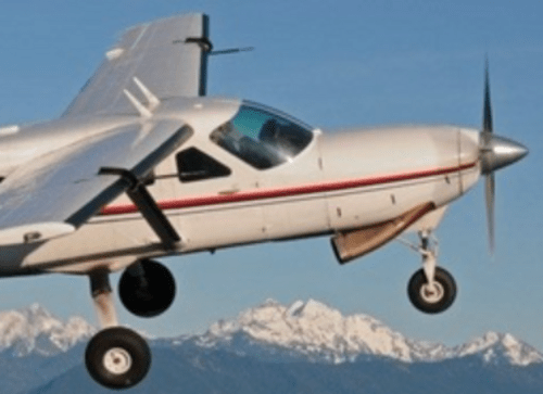
Subsonic- NACA Intake Design
Our workflow allows us to define the primary variables of the simulation, using a mathematical formulation to generate a solution where the flow is turbulent and compressible. Our workflow methodology compares favorably with experimental data analysis for the S-duct wall primary variables, such as:
- Pressure
- Temperature
- Velocity
- Plotting Techniques Following the Intake Line, Suitable for Comparison with the Experimental Data
Hypersonic Flow
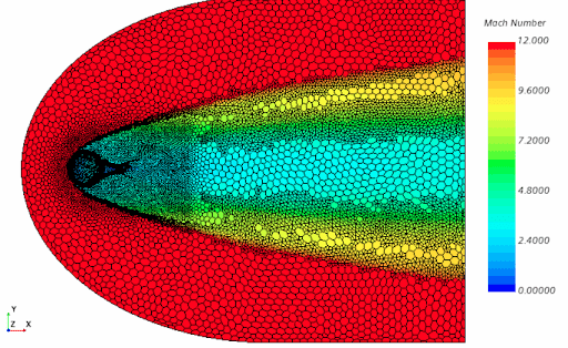
Hypersonic flows and flight envelopes present unique challenges in computational flow dynamics.
Our proprietary workflow is suitable to investigate the following applications:
- Resolving Developing Shocks
- Calculating Compressibility and Thermodynamic Effects of the Hypersonic Flow
- Determine the Capability of A Propulsion System to Efficiently Accelerate the Vehicle
- The Gradient of Mach Number is Used to Build A Polyhedral Mesh Adaption
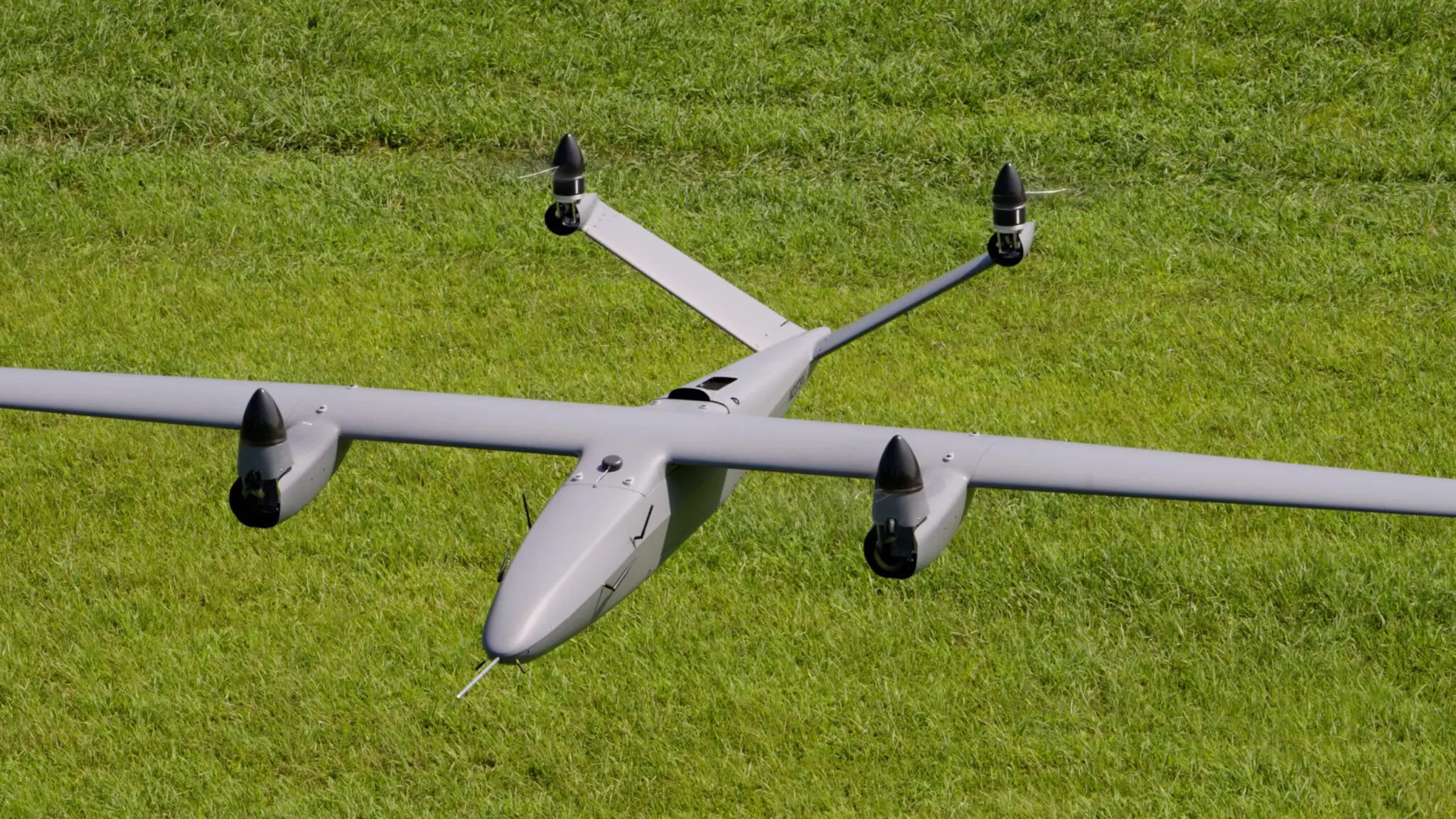
VTOL and Powered Lift Aircraft
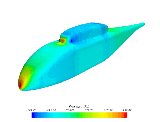
Fuselage Design
Our rotor - fuselage workflow allows us to include operating conditions that exerts a wide range of loads to the fuselage. These loads have an effect on aircraft components:
- Fuselage Bend Downwards From its Support at the Wing
- Wind Loads From the Rotor and Free Stream Velocity
- Pressure Due to Rotor - Fuselage Interaction in Maneuvering Flight and Landing Loads
- Velocity and Wind Forces on the Fuselage Due to A Propeller Vehicle Interaction
- Avoid Forward or an Aft Shift in the Center of Gravity on the Aircraft
- Avoid Normal Stresses to the Structure and Power Plants of the Aircraft in Addition to Adverse Effects on the Flight Performance
Control Surfaces
Our workflow automatically modifies the values of design parameters and evaluates the resulting lift and drag coefficients of a control surface design. By adjusting the position of the leading and trailing flaps configurations we can help our customers to evaluate designs as follows:
- Optimize Flaps Based on Objectives
- Maximize Lift While Minimizing Drag
- Reduce Flutter Potential that Could Destroy the Wing
- Explore Over 120 Designs with the Optimization Tool
- Set Design Parameters to Control the Position of the Airfoil Flaps
Sonic Boom
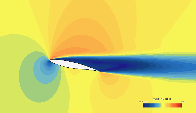
Our workflow allows us to include operating conditions where shock waves takes place and determine the final distribution of the pressure coefficient on the airfoil. Suitable to calculate:
- Over-Pressure Impact to the Area Exposed to the Sonic Boom
- Capture Air-Pressure Waves Location
- Reduce Noise Pollution
- Visualize Results Suitable to Compare with Experimental Data
- Intensity and Width of A Sonic Boom
- Physical Characteristics of the Aircraft to Determine Shock Wave Location
- Investigate Aircraft Operating Conditions to Mitigate Sonic Boom

Unmanned Systems
Drone Propeller Performance
TotalSim workflow uses meshing techniques for complex aerospace geometries such as wings, propeller blades or turbine blades. This generates a very fine mesh that adequately captures the curvature of the leading and trailing edges for aerodynamics effects.
Our proprietary workflow allows us to help you do the following:
- Predict the Speed At Which An Unmanned Vehicle Moves Through Air in Response to the Thrust Supplied by a Spinning Propeller or Turbines
- Calculate Propeller Effects on Aircraft Performance Due to Pressure Gradients
- Run A Digital Wind Tunnel Aerodynamics Analysis for Over 120 Configurations at the Same Time
Aero Mapping of Flight Envelope
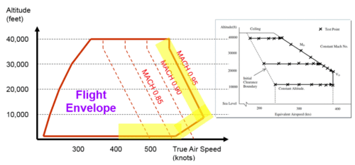
Aero Mapping of Flight Envelope
Ground Vibration Tests (GVT) and flutter tests are used to define a safe flight envelope for a given aircraft configuration. TotalSim CFD dedicated workflow is used to determine this envelope by doing the following:
- Calculating Resonant Frequencies, Mode Shapes and Damping
- Modeling Technology in Aerodynamic and Structures Effects for Flutter Prediction
- Evaluate Performance of the Aircraft Design at Different Altitudes
- Determine Needed Power for A Particular Aircraft Under Certain Conditions to Construct A Flight Envelope
- Calculate the Relation Between Speed at Level Flight and Altitude to Determine the Ideal Flight Altitude per Aircraft Configuration
The aerodynamic model is verified by wind tunnel testings, while the structural model is verified by GVT testing.
Aerodynamics - Multiphase
Airfoil Icing
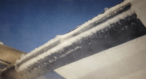
The prediction of ice when droplets form an ice layer on the aircraft surface is key to calculating aerodynamic properties of the wing. For this complex physics simulation our workflow contains technology in fluid film, dispersed multiphase and multiphase interaction.
The process is as follows:
- Multiphase Mixture of Air and Water Droplets
- Droplet Phase is Transferred to the Surface of the Airfoil as A Liquid Film
- Shell Region with Fluid Film Properties is Created on the Surface of the Airfoil
- Shape of the Airfoil Must Change as more Ice is Formed
Structural Loading
Wind Loading
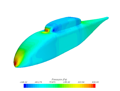
Our rotor - fuselage workflow allows us to include operating conditions that exerts a wide range of loads to the fuselage from a variety of sources to calculate:
- Fuselage Bend Downwards From its Support at the Wing
- Wind Loads from the Rotor and Free Stream Velocity
- Pressure Due to Rotor - Fuselage Interaction in Maneuvering Flight and Landing Loads
- Velocity and Wind Forces on the Fuselage Due to a Propeller Vehicle Interaction
- Avoid Forward or an Aft Shift in the Center of Gravity on the Aircraft
- Avoid Normal Stresses to the Structure and Power Plants of the Aircraft in Addition to Adverse Effects on the Flight Performance
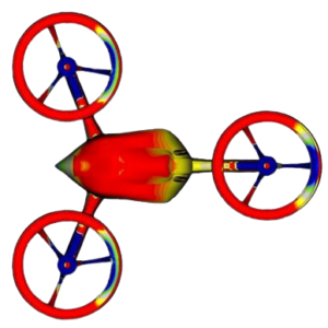
Rotational Loads
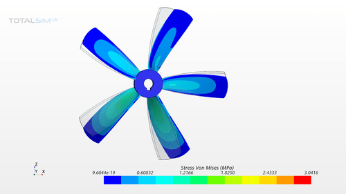
Due to rotational movement of a structure, it can experience structural stresses for example, a rotating fan experiences high stresses in the hub region. Our rotational Load workflow can model such loads for structural analysis.
- Stress Due to Rotational Loads
- Blade Deformation
- Strain at the Blade-Hub Connection
- Internal Force - Forces on Inner Area of the Hub
Propulsion Systems
Propeller and Rotor Systems
Aerodynamics
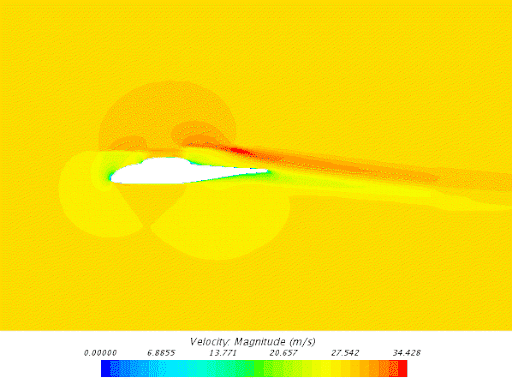
Our simulation workflow includes complex and simplified physics models to understand the behavior of wind motion around the rotating system for the resolution of blade geometry, or by imposing a pressure jump across a plane surface.
Our workflow can be used for the following:
- Model Propellers and Rotor systems
- Evaluate the Effect of Rotating Machinery on the Surrounding Flow Field
- Impose a Pressure Jump Across A Plane Surface
- Used for Pumps, Propellers, Fans and Wind Turbines
Aeroacoustics
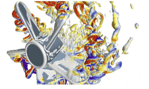
- Near Field and Far Field Broadband Noise
- Fan Noise
- HVAC Duct Noise
- Gap Noise
- Whistle Noise
- Acoustic Treatments
- Sound Reduction Performance (Transmission Loss) in Mufflers
Power Plants
Internal Combustion Engine (ICE)
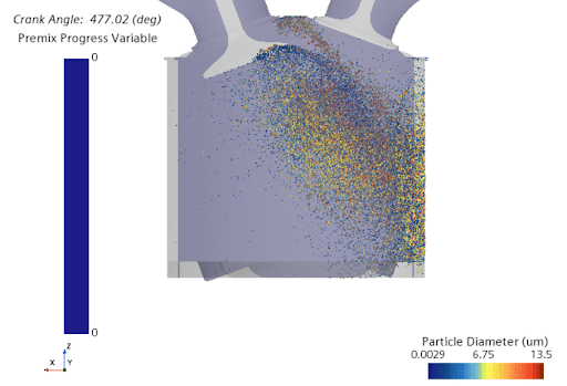
This workflow predicts the turbulence kinetic energy, until ignition point, in a single cylinder of a motored gasoline engine.
Our proprietary workflow allows us to help you do the following:
- Simulate the Intake and Compression Stroke in A Gasoline Engine
- Model Air as A Multi-Component Gas Mixture
- Model the Motion of the Piston and the Valves
- Optimize Piston Temperature Due to Internal Engine Combustion
Electric
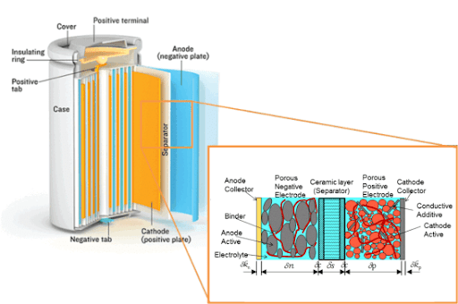
Our li-Ion battery cell workflow allows us to ensure that your li-Ion battery cell design operates efficiently at the micro-scale level.
Our proprietary workflow allows us to help you identify the following:
- Microstructure of Porous Battery Electrodes
- Determine Li-Ion/Salt Concentration in the Active Materials
- Electric Current Density
- High Current Density at Locations of Interest
Thermal Management
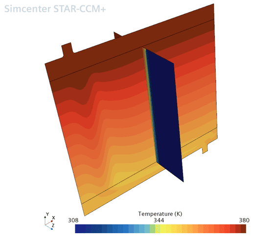
With our heat exchanger workflow we help customers calculate external air flow and coolant-side temperature distributions throughout the heat exchanger dual method.
Our workflow helps you do the following:
- Calculate Conductive Heat Transfer Inside the Radiator
- Calculate Convective Heat Transfer Within the Engine Bay
- Complete Temperature Profile from the Dual Stream
- Full Vehicle Analysis - Assess Performance Impact of Bodywork
Turbomachinery
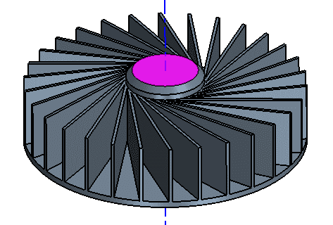
Our proprietary workflow on harmonic balance allows us to investigate the following between blades:
- Harmonic Balance
- Compressible Gas Properties
- Turbulence
- Complex Aerodynamic and Thermodynamic Interactions
- Flow and Thermal Analysis Methods to Improve Design Process
- Turbine Blade Metal Temperature
Fuel Systems
Filling and Transfer Systems
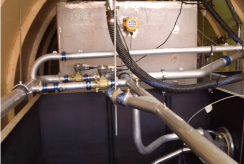
Totalsim 's workflow for filling a tank helps our customers calculate the following:
- Avoid Damage to the Tank Structure Due to Liquid Impact on the Tank Walls
- Optimize Inlet Location
- Nozzle and Mass Flow Rate Optimization
- Calculate Pressure as Liquid Enters and Gas Leaves the Tank
- Calculate the Increase or Decrease of Liquid Volume Due to Temperature Changes to Avoid Errors in Fuel Indication
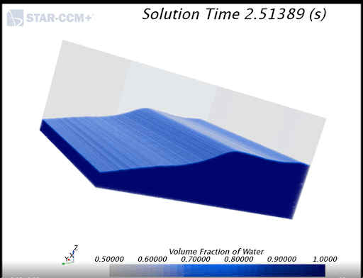
Tank Sloshing
Our CFD tank sloshing workflow allows us to ensure that our customers tank design operates efficiently at different velocities scenarios, temperatures and pressures.
Our proprietary workflow helps you with the following:
- Unsteady Acceleration in the Horizontal Direction that Causes the Liquid to Slosh from Side to Side Inside the Container
- Modeling the Bulk Movement of the Water and to Track the Liquid-Air Interface to Calculate Pressure on the Tank Walls
- Small-Scale Flow Features such as Droplets and Bubbles to Account for the Right Volume of Liquid Exerting Pressure on Tank Walls
- Volume Fractions of Air-Liquid to Assess Correctly the Volume of Liquid During Acceleration or Decrease of Speed.
- Mitigate Sloshing by Optimizing Number of Baffles
Cabin Systems
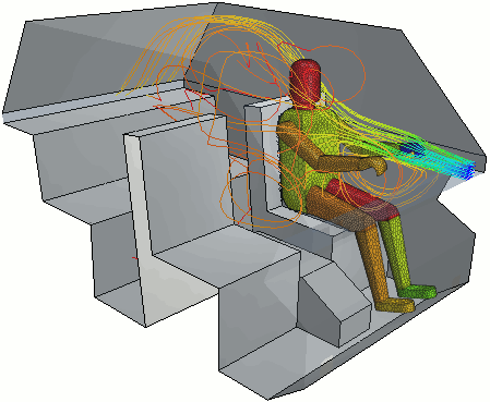
Comfort / HVAC
Our aircraft solutions workflow for passenger thermal management has been designed for the aerospace industry to optimize cabins areas for increased passenger safety and comfort:
- Passenger Metabolic Rate, Body Size and Clothing Resistance
- Humidity
- Natural Ventilation and Vessel Motion
- HVAC
- Solar Loading
- Optimized Thermal Comfort for Passengers Cabins in Aircraft
Aeroacoustics
Our proprietary workflow allows us to help customers to reduce noise pollution by calculating the noise sources:
- Near Field and Far Field Broadband Noise
- Fan Noise
- HVAC Duct Noise
- Gap Noise
- Whistle Noise
- Acoustic Treatments

Solar Loading
TotalSim uses an automatic tool to simulate the behavior of a thin glass transmitting most solar radiation while absorbing most infrared. We then calculate an overall heat transfer by different heat transfer mechanisms such as conduction, multi-band, thermal radiation and solar load.
Our workflow includes capabilities for:
- Aircraft Cockpit
- Commercial Airplane Passengers Thermal Comfort
- Airport Gates Thermal Comfort

Space Systems - Launch Systems
Ground Launch
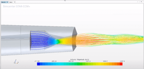
Our proprietary workflow is an automatic tool used to assess nozzle and rocket designs for thrust versus payload. This is based on rocket motor and engine characteristics and considers the trajectories on mission requirements.
Our workflow includes capabilities for:
- Thrust vs Payload Performance
- Self Propulsion Nozzle Assessment
- Predicts the Speed With Which A Rocket Moves Through Air in Response to the Thrust Supplied by a Particular Motor with A Particular Nozzle
- Thrust Generated from A Solid Rocket Motor Based on Nozzle Configurations
- Nozzle Design
- Drag Forces on Rocket body and Re-entry Vehicles
Air Launch
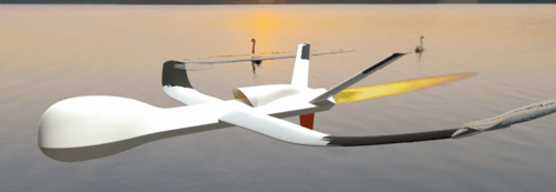
TotalSim uses an automatic tool to assess nozzle thrust performance at different heights and velocity launch maneuverability. This is based on motor or engine capabilities along with nozzle designs.
Our workflow includes the following capabilities for missiles:
- Design
- Drag Reduction
- Self Propulsion Missile Assessment Workflow
- Predicts the Speed With Which An Aircraft Moves Through Air in Response to the Thrust Supplied by A Particular Motor with A Particular Nozzle
- Nozzle Design
Space Aerodynamics
Control Surfaces
Our workflow automatically modifies the values of design parameters and evaluates the resulting lift and drag coefficients of a control surface design. By adjusting the position of the leading and trailing flaps configurations we can help our customers to evaluate designs as follows:
- Optimize Flaps Based on Objectives
- Maximize Lift While Minimizing Drag
- Reduce Flutter Potential that Could Destroy the Wing
- Explore Over 120 Designs with the Optimization Tool
- Set Design Parameters to Control the Position of the Airfoil Flaps
Thermal Management - Hypersonic Atmospheric Re-Entry Vehicle
Hypersonic flows and flight envelopes present unique challenges in computational flow dynamics.
Our proprietary workflow using StarCCM+ is suitable to provide solutions for the following hypersonic effects:
- Resolving Developing Shocks
- Compressibility and Thermodynamics Effects of the Hypersonic Flow
- Designing Nozzle Based on Thrust Requirements

Find out how you can save time and money with TotalSim's Aerospace Industry CFD Solutions.
"*" indicates required fields
