EV Powertrain CFD
EV Powertrain
Powertrain development for hybrid and electric vehicle is pushing engineering complexity to new paradigm. In order to evaluate performance levels during integration all combustion engines, e-machines, batteries, generators and electrical wiring harness have to be studied individually and as a system. Integrating battery, electric motors, inverters and generators with all other vehicle sub-systems at early stages of the design cycle allows the capture of global energy distribution and NVH performance for optimized attributes balancing.
Explore our electric vehicle workflows and the capabilities they can assist you with below!
Totalsim Workflows in Computational Fluid Dynamics as an EV Powertrain Design Tool:
TotalSim's motor-sport technology has been borrowed for the construction of EV workflows that require the use of complex computational fluid dynamics. TotalSim's workflows create a digital twin to the EV design process. Our technology was born in the automotive F1 race track and can be employed to address critical EV Powertrain issues.
The following workflow capabilities provide an overview of what can be accomplished when using our StarCCM+ workflows for the most complex challenges that necessitate CFD technology.
Benefits We Provide
Working with virtual modeling and simulation of fluid flows allows you to accelerate your design process using software such as Star-CCM+ or OpenFOAM. This reduces the number of physical prototypes and testing, while still evaluating all necessary conditions. Our engagement ranges from CFD consulting, to training, to customized workflows to meet your specific needs.
Our Strategic Partnership With AltaSim Takes EV Simulation to the Next Level
Download Our Brochure
Explore Our EV Powertrain Capabilities
Thermal
Heat Exchanger
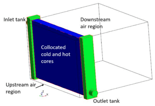
With our heat exchanger workflow we help customers calculate external air flow and coolant-side temperature distributions throughout the heat exchanger.
Our workflow helps you do the following:
- Calculate Conductive Heat Transfer Inside the Radiator
- Calculate Convective Heat Transfer Within the Engine Bay
- Complete Temperature Profile from the Dual Stream
- Full Vehicle Analysis - Assess Performance Impact of Bodywork

Gerotor Pump
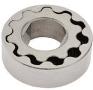
Our proprietary workflow for gerotor pumps help our customers calculate the following:
- Optimize Tooth Count and Shape

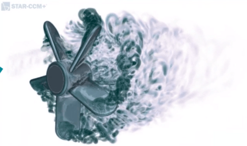
Fans and Ducts
The axial fan analysis solution helps calculate the following:
- Predicting the Pressure Rise Through A Fan in your System
- The Solution can Model the Swirl that is Introduced by the Fan
- Fan Blades Performance Analysis

Electronics Cooling
Our proprietary workflow in StarCCM+ provides an automated methodology which allows us to help our customers with devices that rely on natural convection only. The electronics cooling toolset includes the JEDEC method for estimating cooling due to:
- Conduction in the Solid Components of the Test Rig, the Chip Package and the Chamber
- Diffusion, Natural Convection and Radiation Determination within the Enclosed Region
- Measure the Junction-to-Ambient Thermal Resistance of a Chip Package in a Standardized Still Air Environment


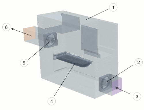
Multi-Part Solid: Graphics Card Cooling
Our proprietary workflow provides an automated methodology that helps our customers analyze multipart solid heat transfer in a single region.
Our workflow does the following:
- Calculates Convective Heat Transfer Inside the Case
- Calculates Conductive Heat Transfer Between the Solid Parts in Contact, like the Components Inside the Graphics Card
- Applies Different Heat Sources on Parts in A Single Region
- Fans are Represented by Fan Interfaces
- Calculates the Thermal Profile through the PCB Layers

Graphics Card Cooling
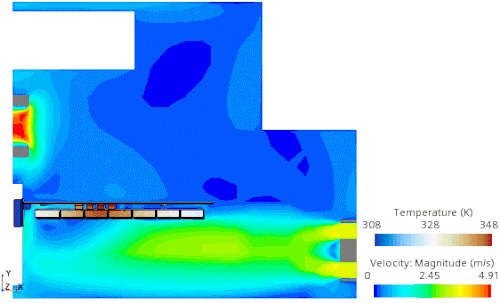
Our proprietary workflow provides an automated methodology that allows us to help our customers calculate the drive of fans flow inside the case. This cools the card and calculates the following:
- Optimized Position of Fans that Cool Electronic Components
- The Impact Fans have on Removing Heat
-
Conduction in the Solid Components of the Graphics Card and the Fans
-
Diffusion and Forced Convection in the Enclosed Air.
- Compare Multiple Arrangements to Determine Best Performance

Structural
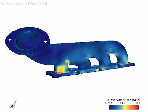
Thermal Stresses
Our workflow allows us to help customers compute the temperature distribution throughout a solid component. We do this by running a finite volume conjugate heat transfer analysis and mapping the temperature data onto a finite element model of the solid design.
Our stress analysis workflow does the following:
- Evaluates Solid Deformation Due to Heat
- Evaluates Solid Material Integrity Due to Thermal Stress
- Gains Insight on Solid Thermal Behavior for Design Features

Rotational Loads
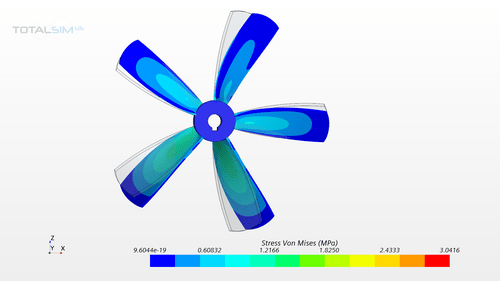
Due to rotational movement of a structure, it can experience structural stresses for example, a rotating fan experiences high stresses in the hub region. Our Rotational Load Workflow can model such loads for structural analysis:
- Stress due to Rotational Loads
- Blade Deformation
- Strain at the Blade-Hub Connection
- Internal Force- Forces on Inner area of the Hub

Battery
Battery Module: Cell Thermal Analysis
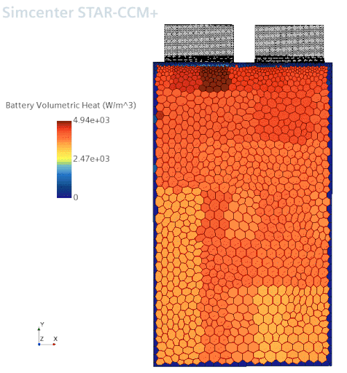
Our cell thermal analysis workflow allows us to help clients simulate battery heat generation that occurs during a certain period of time of a discharge cycle. Our workflow accomplishes the following:
- The Addition of More Cells in A Series to Investigate the Impact of Heat Generation
- Simulation Using A Voltage Plot to Monitor the Battery Discharge During the Cycle
- Results Display How Battery Heat Generation is Distributed on the Battery Cells
For Cylindrical Cells:
- Cylindrical Cells are Connected in Series and are Discharged for A Period of Time With A Certain Load in Amperes
- Configuration of Cylindrical Battery Cells Using A Staggered Configuration with Uniform Spacing
- Results Model the Heat Generation in the Battery and the Air Flow in the External Casing

Li-Ion Electrochemistry Analysis
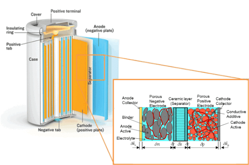
Our li-Ion battery cell workflow allows us to ensure that your li-Ion battery cell design operates efficiently at the microscale level.
Our proprietary workflow allows us to help you do and identify the following:
- Microstructure of Porous Battery Electrodes
- Determine Li-Ion/Salt Concentration in the Active Materials
- Electric Current Density
- Identify High Current Density at Locations of Interest

Fuel Cell
Solid Oxide Fuel Cells (SOFCs)
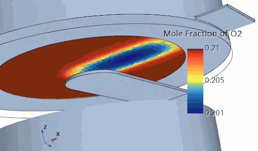
Our workflow for solid oxide fuel cells is able to calculate the chemical energy that is released by electrochemical reactions and convert it to electrical energy. Our customers benefit from our workflow to calculate:
- Concentration of Oxygen Across the Porous Cathode
- Reaction Rate with Respect to Oxygen
- Oxygen Diffusion Rate through the Cathode
- Electrical Currents Value
- Calculate External Power Generated
- Calculate the Balance of the Species Masses with the Ones Entering the Fluid Streams

Proton Exchange Membrane Fuel Cell
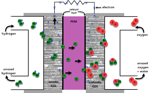
Proton Exchange Membrane (PEM) fuel cells convert chemical energy into electrical energy by spatially separating electrochemical reactions. Our workflow helps our customers to calculate:
- PEM Fuel Cells that are Useful for Powering Low Temperature Applications in Portable Devices
- Devices in the Transport Industry
- Determine if the Electric Current Density is Consistent Throughout the Membrane
- Determine the Volume Fraction of Liquid
- Temperature Profile
- Visualize Saturation Plots when the Maximum Saturation Level becomes Consistent in the Simulation

Driveline Lubrication
Gears Lubrication
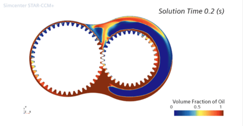
An optimally designed automotive gearbox can result in energy savings, reduced environmental impact and increased reliability. Along with other components of the gear case, efficiency isa major concern in the design of transmissions. The churning power losses associated with the motion of gears through the oil represent a significant portion of the total power losses in a transmission and therefore need to be estimated using our proprietary workflow in gear dynamics. This workflow allows us to help you with the following:
- Verify the Distribution of Oil around the Gears
- Visualize Oil and Air Distribution as Gears Rotate
- Windage
- Churning
- Pocketing
- Transmission Efficiency
- Heat Transfer

Electric Motor
E-Powertrain Simulation
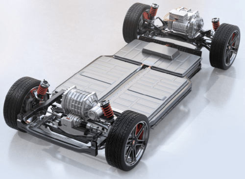
Our proprietary workflow provides an automated methodology that allows us to help customers in simulation for power electronics balance driving comfort, range and cost with energy and thermal management. This improves quality and prevents failure by meeting the following key benefits of our workflow:
- Integrate Energy Usage and Thermal Management, Evaluate Multiple Architectures and Balance Performance Early in Development
- Achieve Superior Sound Quality, Balance Noise Contributions and Integrate Acoustic Vehicle Alerting Systems (AVAS) for Passenger and Pedestrian Safety
- Minimize Aerodynamic Energy Losses and Optimize Power Consumption for Maximum Range and Comfort.
- Mitigate Electro-Magnetic Interference and Identify Design Trade-offs Taking Space, Weight and Cost Constraints into Account

Induction Systems - Magnetohydrodynamics
Our proprietary workflow allows our customers to account for the interaction between the conducting fluid and the magnetic field. We can assist you with the following applications:
- Electric Current Flowing Through the Coils that Acts on the Electrically Conducting Fluid and Stirring the Metal
- Performing the Electromagnetic Analysis using the Harmonic Balance FV Transverse Magnetic Potential Model
- Molten Metals, Electrolytes and Plasma
- Calculate Lorentz Forces in Both the Fluid Flow Solution and the Electric Potential Solution
