TotalSim Automotive Industry CFD Solutions
Totalsim’s dedicated solutions for the automotive industry enable you to account for all aspects of auto performance. We easily visualize results helping you to evaluate and improve your designs. Explore our Automotive capabilities below.
Simulate at full scale in real conditions – Make decisions based on data you understand
Automobile makers continuously face the challenge of having to introduce new products to the market at an accelerated pace. In order to speed up the process of product development, it is crucial for designers and engineers to have the ability to:
- Generate and evaluate numerous design configurations beforehand
- Select the most competitive features to be developed
- Virtually validate designs to avoid design flaws prior to creating physical prototypes
Benefits We Provide
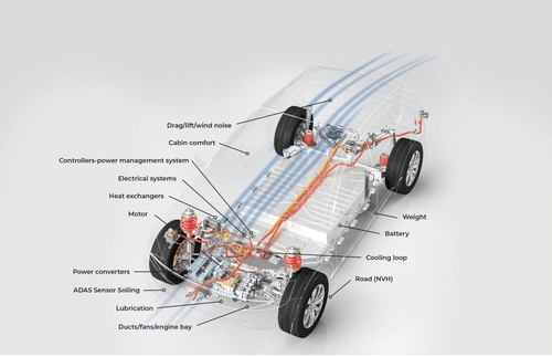
Working with virtual modeling and simulation of fluid flows allows you to accelerate your design process using software such as Star-CCM+ or OpenFOAM. This reduces the number of physical prototypes and testing, while still evaluating all necessary conditions. Our engagement ranges from CFD consulting, to training, to customized workflows in order to meet your specific needs.
Our high volume workflows allow you to run flow analysis on different product configurations with minimal effort. This capability allows us to help you do the following:
- Explore multiple designs of a particular part for a design manager study
- Replace part capability to run a series of analyses in which the part is changed each time
- Explore as many designs as your timeline and budget allow
Our personalized simulations and apps provide valuable insights to help save time and money during everything from wind tunnel testing to internal combustion. Working with TotalSim will put you years ahead of the competition, while lowering your costs and optimizing your designs. Let us help you reach your goals efficiently and accurately.
Learn More About Our Automotive Capabilities
Chassis
External Aerodynamics
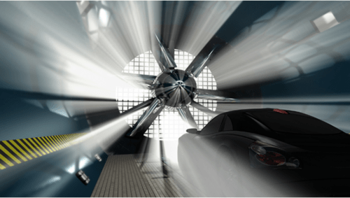
Our simulation workflow for external aerodynamics can be used to replace or augment wind tunnel testing. We use a range of physics models to understand the behavior of wind and motion on the airflow around a vehicle. This includes:
- Lift and Drag Forces
- Intake Positioning
- Exhaust Plume Tracking
- Cooling
Aeroacoustics
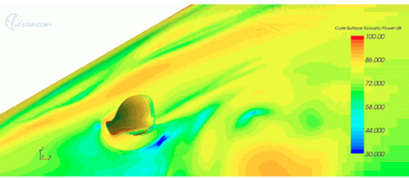
Our proprietary workflow allows us to help customers assess the following:
- Near Field and Far Field Broadband Noise
- Fan Noise
- HVAC Duct Noise
- Gap Noise
- Whistle Noise
- Acoustic Treatments
- Sound Reduction Performance (Transmission Loss) in Mufflers
Cooling
Powertrain
Our dedicated workflow has a complete suite of multiphysics models ranging from conjugate heat transfer to multiphase flows. This helps our customers to design the following:
- Water Jackets
- Heat Shields
- Exhaust Manifold
- Catalytic Convertors
- Gearbox
- System Level Interactions
Heat Exchanger
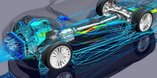
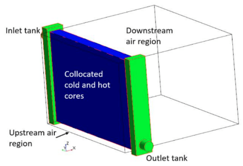
With our heat exchanger workflow we help customers calculate external air flow and coolant-side temperature distributions throughout the heat exchanger.
Our workflow helps you do the following:
- Calculate Conductive Heat Transfer Inside the Radiator
- Calculate Convective Heat Transfer Within the Engine Bay
- Complete Temperature Profile from the Dual Stream
- Full Vehicle Analysis - Assess Performance Impact of Bodywork
Brake Systems
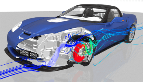
Our proprietary workflow for convective heat transfer helps our customers to calculate the following:
- Heat Generation in Brake Rotors
- Brake Duct Cooling Performance
- Brake Fluid Boiling
- Convection, Conduction, Radiation and Conjugate Heat Transfer Workflow Capabilities
- Cooling Trade Offs with Rotor Cross Drilling and Vane Design
Lighting Systems
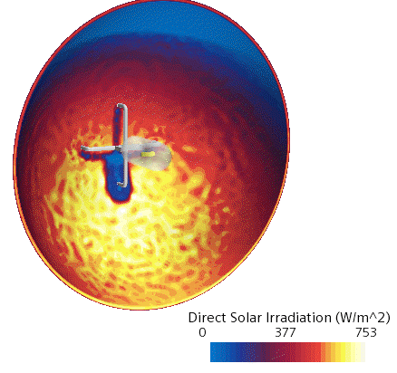
Correctly predict the temperature field and critical spots that could damage the headlamp by modeling all the physics taking place inside it.
Our workflow measures the minimum and maximum temperatures of the headlamp along with the following components:
- Air Temperature
- Halogen Bulb Temperature
- Lens Temperature
- Housing Temperature
Cabin
HVAC
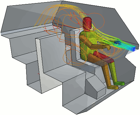
Our workflow for thermal comfort management helps our customers to optimize the vehicle for passenger comfort. This includes:
- Passenger Metabolic Rate, Body Size and Clothing Resistance
- Humidity
- HVAC
- Solar Loading
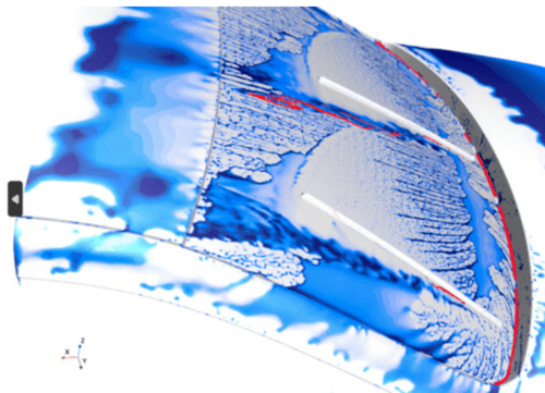
Defrosting and Defogging
The prediction of ice melting and refreezing or droplets evaporating and condensing can be simulated with our proprietary workflow.
The process captures:
- Evaporation Rate from Thin Water Films
- Condensation Seeding
- Melting and Solidifying of the Ice/Liquid Film
- Heat Transfer
Water Management
Windshield Wipers, Side Mirrors, Fording
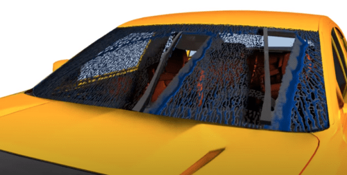
Our proprietary workflow combines the capabilities of several different multiphase models to widen the range of real life multiphase flows you can simulate. This allows us to help you with the following applications:
- Vehicle Water Management:
- Windshield Wipers
- Side Mirrors
- Fording
- Oil Jet Cooling in Electric Motors
- Multiphase Pumps
Soiling
ADAS Sensors
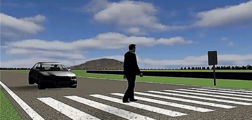
Correlate virtual test scenarios with physical testing, car testing and sensors to validate automated driving functions. Our workflow helps customers with:
- Verification and Validation of ADAS
- Construction of Digital Twins
- Virtual Test Scenarios Definition
Soiling
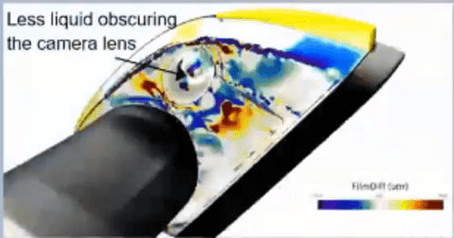
Our proprietary workflow allows us to accurately predict soiling patterns and the impact of dust and dirt on camera visibility and sensor performance. Our workflow includes the following:
- Dust Ingress and Self-Soiling Analysis
- Camera Soiling
- Sensor Soiling
Structural Loading
Rotational Loads
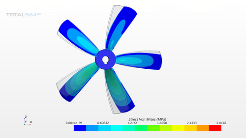
Due to the rotational movement of a structure, it can experience structural stresses. For example, a rotating fan experiences high stresses in the hub region. Our rotational load workflow can model such loads for structural analysis.
- Stress Due to Rotational Loads
- Blade Deformation
- Strain at the Blade-Hub Connection
- Internal Force- Forces on Inner Area of the Hub
ICE Powertrain - Cooling Systems
Heat Exchanger Dual Stream
Our heat exchanger interface calculates the contribution from the air and the coolant using a dual stream option for the heat exchanger method. Our workflow allows us to do the following:
- Calculate Air-Core and Coolant-Core Regions Treated with Porous Technology
- Find Accurate Heat Transfer Between Solid and Liquid Regions
- Use Measured Heat Exchanger Efficiencies using a UAG Table

Rotational Internal Flow
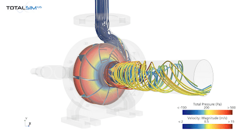
This workflow allows us to help customers explicitly model their pump design and assess its performance. The full range of pump capabilities include:
- Find Net Positive Suction
- Optimize Water Pump Case
- Optimize Impeller
- Test Blade Shape Angles
- Estimate Water Pump Efficiency
Fin Cooling
Our proprietary workflow for conjugate heat transfer and convection heat transfer combines methods to calculate the cooling performance of adding fins to hot solid components such as gear casing, pumps and alternators . Our workflow helps measure the following:
- Conduction
- Diffusion
- Natural Convection
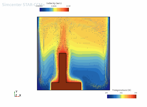
Cooling Clutch Using Conjugate Heat Transfer
Our proprietary workflow for convective heat transfer and conjugate heat transfer helps our customers calculate the following between solids & solids, fluids & fluids and solids & fluids:
- Convection
- Conduction
- Radiation
- Heat Transfer Interactions
Electronics Cooling
Our proprietary workflow in StarCCM+ provides an automated methodology that helps our customers with devices that rely only on natural convection. The electronics cooling toolset includes the JEDEC method for estimating cooling due to:
- Conduction in the Solid Components of the Test Rig, the Chip Package and the Chamber
- Diffusion, Natural Convection and Radiation Determination Within the Enclosed Region
- Measure the Junction-to-Ambient Thermal Resistance of a Chip Package in a Standardized Still Air Environment

In-Cylinder
Intake Ports & Valves
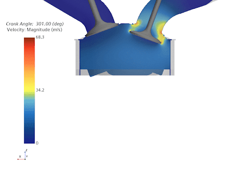
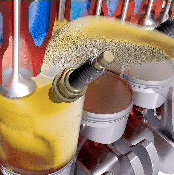
Predict the progress of tumble and turbulence kinetic energy in a single cylinder of a motored gasoline engine up to the ignition point. Our proprietary workflow allows us to help you do the following:
- Simulate the Intake and Compression Stroke in a Gasoline Engine
- Model Air as a Multi-Component Gas Mixture
- Model the Motion of the Piston and the Valves
- Set the Length of the Connecting Rod, Which Directly Affects the Piston Motion
Gasoline Engine Combustion
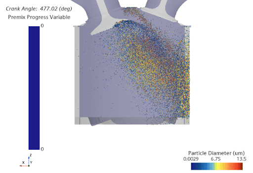
Simulate the combustion process in a gasoline engine using the Extended Coherent Flame Model Three Zone (ECFM-3Z). Our proprietary workflow allows us to help you with the following:
- Flame Propagation
- Diffusion Combustion
- Spark Ignition and Combustion Process
Fuel Injection
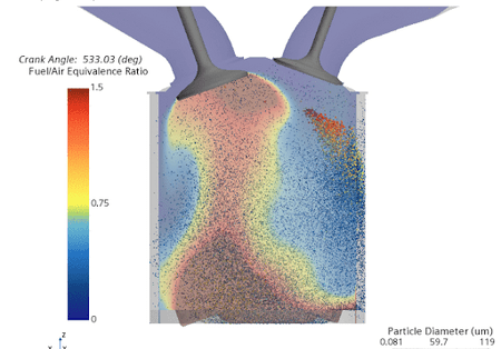
The purpose of this workflow is to predict the charge motion in an internal combustion engine. Our proprietary workflow allows us to help you do the following:
- Investigate the Spray Formation Resulting from a Direct Fuel Injection
- Predict the Mass of Vapor Arising from the Injected Fuel and the Liquid and Vapor Spray Penetration
- Calculate Fuel to Air Equivalence Ratio in the Cylinder
- Calculate Formation and Transport of Fuel Film on the Cylinder Walls
Diesel Engine: Closed-Cycle Sector Model
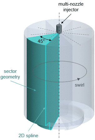
This CFD workflow will perform a closed-cycle analysis of a diesel compression-ignition engine. Using the Extended Coherent Using the flame model with combustion limited by equilibrium enthalpy (ECFM-CLEH) to simulate the combustion process, we can help you with the following:
- Injection
- Ignition
- Combustion Process in an Engine Cylinder with All Intake and Exhaust Valves Closed
Lubrication Systems
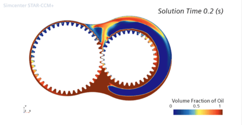
Gears Lubrication
An optimally designed automotive gearbox can result in energy savings, reduced environmental impact and increased reliability. Along with other components of the gearcase, efficiency is also a major concern in the design of transmissions. The churning power losses associated with the motion of gears through the oil represent a significant portion of the total power losses in a transmission and therefore need to be estimated using our proprietary workflow in gear dynamics. This allows us to help you with the following:
- Verify the Distribution of Oil around the Gears
- Visualize Oil and Air Distribution as Gears Rotate
- Windage
- Churning
- Pocketing
- Transmission Efficiency
- Heat Transfer
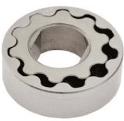
Gerotor Pump
Our proprietary workflow for gerotor pumps help our customers calculate the following:
- Optimize Tooth Count and Shape
Intake system
Manifolds
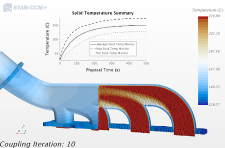
Our proprietary workflow in StarCCM+ provides an automated methodology that allows us to help customers assess systems across multiple time-scales in a single simulation such as the heating of an exhaust manifold. For multi-time scale conjugate heat transfer analysis we help you calculate the following:
- Conjugate Heat Transfer (CHT) Application
- Optimized Sensor Locations
- Multi Time Scale CHT
- Transient-Transient Multi Time Scale CHT
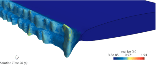
Ice accretion at intake systems and manifolds can adversely impact a cars engine efficiency and performance.
The accretion workflow models the transformation of snow and ice particles to an ice layer on impact with a surface, thus changing the shape of that surface. The workflow captures the following:
- Pressure Drop Changes
- Duct Area Reduction Due to Ice Build Up
- Airflow Path Change Due to Build Up
Exhaust Systems
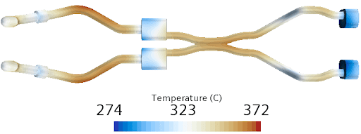
Exhaust Pipe
Our proprietary workflow will calculate the temperature response of thin-walled structures such as exhaust pipes to the hot gases flowing through them. It also allows for conjugate heat transfer simulation including radiation to study the following:
- Heat Shielding
- Thermal Stresses for Lifting and Fatigue
- Fastener and Fixing Locations
- Temperature Management
Catalytic Converter
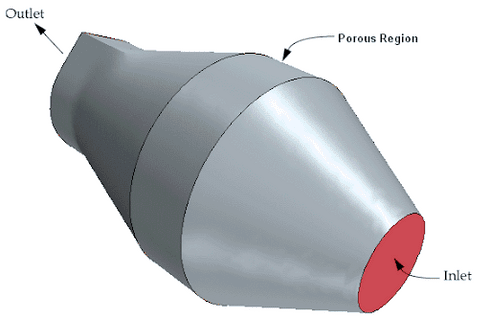
Our proprietary workflow in StarCCM+ provides an automated methodology that allows us to help our customers with a porous media for catalytic simulation. Our workflow for the complex porous media regions allows us to help customers do the following:
- Determine Pressure Drop Per Unit Length
- Validate Resistance Coefficients Based on Isotropic or Orthotropic Flow Characteristics of Your Design
Fuel Systems
Filling
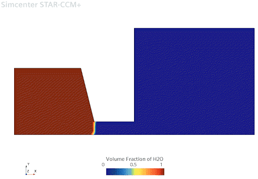
Using Totalsim workflow for tank filling, we will be able to help you calculate the following:
- Gravity-Driven Flow
- Multiphase Simulation
- Water and Air Interaction
- Hydrostatic Pressure Equilibrium
Venting
Our workflow for venting a tank allows us to help you accomplish the following:
- Calculate Excessive Pressure Due to Lack of Vents
- Reduce Pressure on Opening the Fuel Cap
- Reduce the Risk of Fire in Case There is an Ignition Source
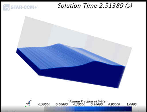
Tank Sloshing
Our tank sloshing workflow helps our customer to avoid instabilities in vehicles and helps calculate:
- Directional Dynamics
- Safety Performance of Highway Tank Vehicles
- Hydrodynamic Forces and Moments Arising from Liquid Cargo Oscillations
- Steering and Braking Maneuvers
- Reduce the Stability Limit and Controllability of Partially-Filled Tank Vehicles
- Unsteady Acceleration in the Horizontal Direction that Causes the Liquid to Slosh from Side-to-Side Inside the Container
- Model the Bulk Movement of the Water and to Track the Liquid-Air Interface
- Small-Scale Flow Features Such as Droplets and Bubbles
- Volume Fractions of Air-Liquid
Structural
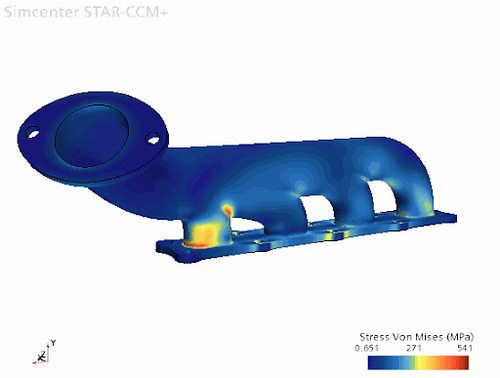
Thermal Stress
Our technology allows us to help customers compute the steady-state temperature distribution throughout a solid design. Our workflow combines conjugate heat transfer analysis and temperature data onto a model of the solid design. Our stress analysis workflow does the following:
- Evaluates Solid Deformation Due to Heat
- Evaluates Solid Material Integrity due to Thermal Stress
- Gains Insight on Solid Thermal Behavior for Design Features
Find out how you can save time and money with TotalSim's Automotive Industry CFD Solutions.
"*" indicates required fields
